I am not a mechanical engineer
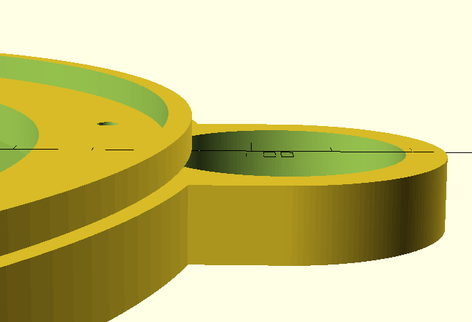
As evidenced by the fact that I generated that model in OpenSCAD. OpenSCAD is a script-based modelling software that has made actual mechanical engineers look at me with a mix of pity and horror.
This project took me a little out of my comfort zone. I went in thinking "it's all applied geometry" and came out thinking "even the stuff that is applied geometry can be hard". In particular, I knew I needed an extremely large gear reduction in both axis to get the precision that would be required. With gears comes an aspect that could make my life difficult: backlash.
Backlash, or more simply "gear slop", is how far the input shaft to a gearbox must turn before the output shaft begins to turn. That distance must be covered every time the input shaft changes direction, and introduced a nonlinearity into the controls. It can be calibrated out, but for smoother movement it's best avoided.
Backlash is controlled by how closely your gears fit, and how "good" your gears are. What makes a gear "good"? As it turns out, there is a particular tooth shape that works best, and the linear dimensions of the shape depend primarily on the number of teeth and the diameter of the gear. It takes a lot of calculations, so naturally I found this wonderful OpenSCAD library that does it all for you.
The other issue that ended up taking more time than expected:
Assembly
The telescope gimbal, mostly disassembled
When you have a 3d-printer and an excess of filament, it's tempting to try to make everything in the fewest number of pieces as possible. After a lot of wasted filament, I found that for complex mechanical assemblies like this it's often better to break up the pieces into logical chunks. That way when some small aspect doesn't work out, you don't have to waste as much time and filament fixing the mistake.
And there were plenty of newbie mistakes. It's so easy to put a bolt somewhere that a tool can't reach. The other easy mistake is to forget about your wire routing. This has bit me before, but thankfully wasn't as important with this design. The general advice is: plan out your wires before printing your first piece!
Now for the gritty details:
The motor drive
As mentioned earlier, I need a large gear reduction. The stepper motors I bought off of sparkfun have 400 steps per revolution, which works out to 0.9º per step. Not small enough! The stepper drivers I bought can drive the steppers in 16-step microstepping mode (which would drive our precision up to 6400 steps per revolution), but it comes at a cost to accuracy and power draw so I tried not to rely on it.
Instead, I used two pairs of gears to get my precision. The first pair is an 8-tooth to 24-tooth bevel gear combination. These give an initial ratio of 3-to-1, and also allow me to change the direction of the rotation for easier motor mounting. the 24-tooth bevel is coupled to a 10-tooth spur that drives a 120-tooth spur. The total ratio of both gear pairs: 36-1, or 14,400 steps per revolution, or 0.025º per step. If needed I can implement microstepping at a later date, which will drive my precision down to 0.001563º per step.
The gear reduction is the same for the azimuth (right and left) and zenith (up and down) directions.
Azimuth drive and the base
To drive the telescope left and right, I mounted it to a large base plate that slides on top of the 120-tooth spur. To facilitate the sliding action, I extruded a ridge from the base plate that slides in an accompanying ledge on the spur gear
This design is simple to print, but it can be be tough to get the tolerances right. Also, the plastic-on-plastic interface is not as good as a bearing. But with such a large circumference to cover, really the only way to make this smoother is to make a channel for individual ball bearings between the two pieces. Given that the only thing holding the pieces together right now is gravity, I wanted to avoid that. But it could be an improvement in the future.
A close up on the azimuth gear assembly
The bevel gear-to-spur gear coupling does use a bearing, supported by the extra "loop" pictured above on the base plate. The small bevel gear is press-fit onto the motor shaft. Currently the press-fit bevel is a weak point in the design, as it occasionally slides loose. A future revision of the gear could include a collar that prevents it from sliding too far back.
Zenith drive
The challenge with zenith (up and down) is that the telescope body can't clip the base, despite needing to rotate a full 90º. One option is to rotate the telescope body around one end, therefore always keeping it away from the base. This causes the center of gravity to shift, however, and I'm not able to print a base large or heavy enough to handle that well. Luckily, my telescope is short enough that I can choose option 2: rotate around the center of gravity. This keeps the weight of the telescope body centered in the same place, but requires the support arms to be taller to keep the telescope away from the base.
A closer view of the support arms
You may notice the 10-tooth spur gear above. Here is how the drive motor mounts on the other side:
No reason not to reuse models here!
The telescope body is a cylinder, and I don't want to drill into it. So to mount it, I took some cues from its stock mount and used a pair of round bands that I could clamp together around the body. This band had to securely connect to the 120-tooth spur, so I ended up with the piece below:
The band prints with two round pegs that fit into the bearings on the arms. To connect the spur to the band, I elongated one of the pegs so it can fit through the spur and the bearing. I then drove a screw through both pieces perpendicular to the axis to keep them together. I added a second screw through the face of the spur into the flat of the band for extra strength, but it may not be needed.
The bearings are super-glued into the arms. The pegs can be inserted into the bearings by bending the arms apart. Once inserted, the arms snap back together with enough strength to make a snug fit.
The entire gear assembly for zenith motion
Electronics Mount
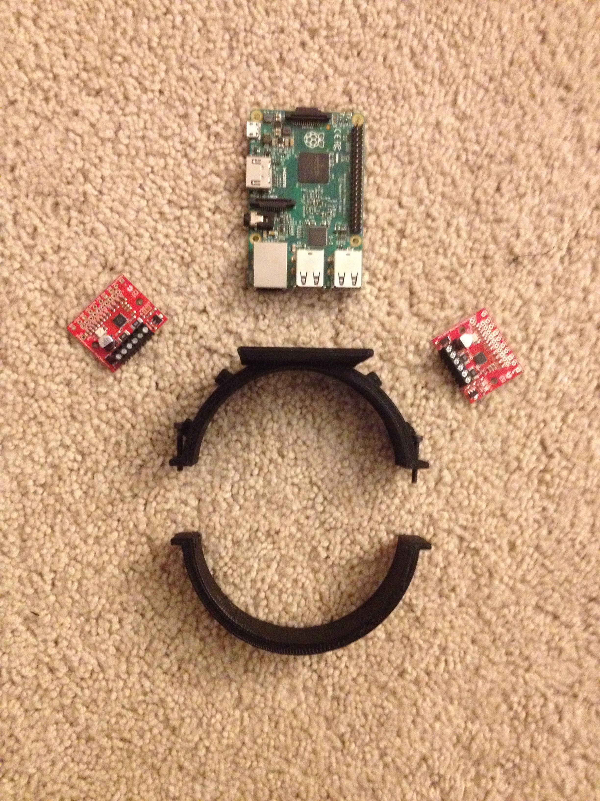
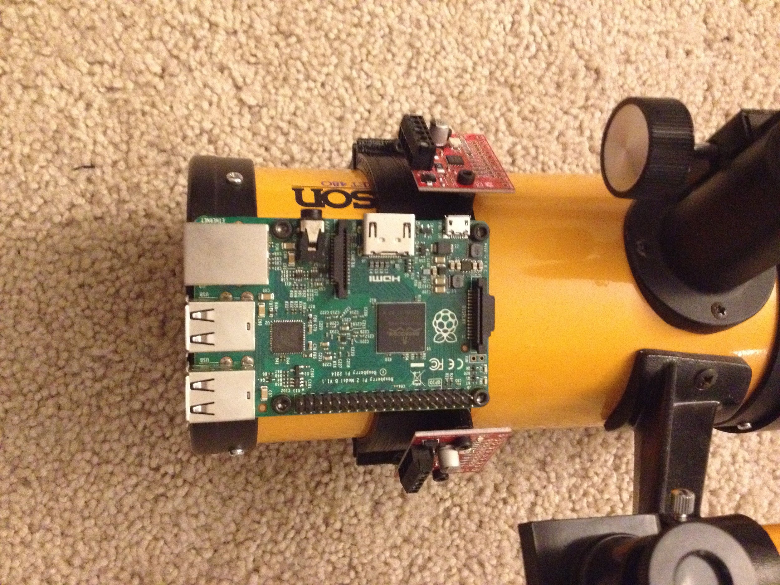
I'll just get this out in the open now: I'm using a raspberry pi for this project. I will get into all of that in the next post. Until then, here's how I mounted it:
Another band of course! this method works pretty well, and doesn't damage the telescope at all. This band has been customized for the electronics pictured above, but it's easy to modify if I want to bolt on additional modules.
And here is the full mechanical assembly, realized in the flesh!
You can find the OpenSCAD files here.


