Hello Everyone! Today’s installment of Spencer’s blog is being written by Halo’s second part, Pierce! I’m the brains behind the mechanical design and implementation of Halo, along with sanity checking all of Spencer’s work. I wanted to write this blog post to discuss the weakest point of the bot from the previous competition: The ring.
The Ring
The chassis of Halo is a unibody construction of 6061-T6 aluminum. We started with a 10” diameter by 1/2” wall aluminum tube that I turned down on my work’s manual lathe. I machined it into a C profile to help reduce the weight. The thickness of the wall is just over 1/8 of an inch thick. We discovered that we were overweight on the initial turning, so I reduced the weight of the ring by approximately 0.25 pounds by adding a 1/4” chamfer at the edges of the bot. This reduced the overall weight of the ring to just under 1 pound. The chamfer is not ideal because it pushes wedges underneath us, but the rapidly approaching impactor helps knock away our problems.
Because of the thin nature of the ring, it introduces us to some structural problems.
The First Impactor
Our first design worked surprisingly well. The first tooth was just a small chunk of 1/2” A36 steel plate that had been trimmed down to save some weight. It was secured to the ring by two grade 5 1/4"-20 hex head bolts. I was immediately worried that the bolts may rip their way through the ring, or crack it in half. Needless to say, I was flabbergasted when the ring survived all the way through the competition. By the end of the competition though, it was cracking right at the base of the impactor.
The ring at the base of the impactor showing deflection and cracking
Now, why was this happening? It couldn’t be because we were slamming into things at 1100 RPM, that’s totally not what would happen…. Okay, I’m joking. The impact force that we are applying every time we smack into something transfers a very large load to the bot. How large of a load? Well, it really depends on multiple factors, mainly how much energy is transferred to the surface we are impacting and the time that the impact lasts for. I decided to do a simple A-B comparison of the strength of the old tooth to the new tooth, so I decided to call the impact load 100 times the weight of the robot, or 300 pounds. I figured that amount should show us some good results on the FEA simulation. You may have heard of the term FEA (or Finite Element Analysis) thrown around. It is a method of simulating the stresses on CAD parts. Most professional CAD packages have some method of doing FEA stress analysis built in. I simplified the model down to a small cross section of the ring with the original tooth. Simplification keeps the simulation run times short and reduces the likelihood that something weird happens. The ends of the ring become our “fixed points” for the FEA simulation, and the tooth is bonded to the ring in this simple simulation (I use a better contact set for the redesign, don’t worry).
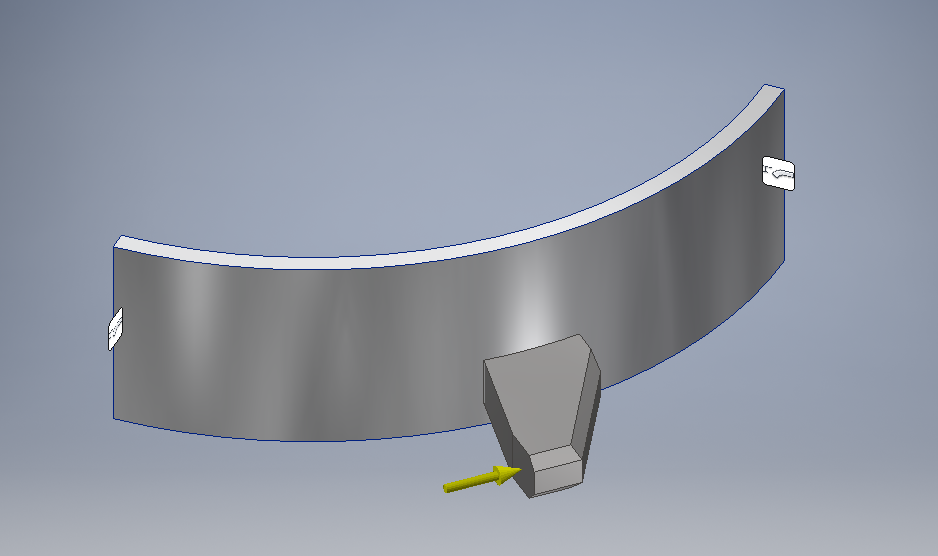
Simplified FEA Model for the First Impactor
Once all of the materials are defined, and I ran the simulation, I got results that I expected. The ring showed stress concentrations right around the tooth, with the ring deforming into the S-shape which is slightly visible in the after competition image above.

Original Tooth FEA with Von Mises Stress
Okay, but what does this actually mean for our impacts? How close are we to actually causing damage to the ring? For that, I switched into the Factor of Safety (FOS) view. This shows how close each piece is to experiencing plastic deformation (the technical term for when something actually stays bent). The view is effectively dividing the shown stress by the yield strength. An FOS of 1 means that the material will survive if everything in the model is exactly correct with no simulation inaccuracies. Obviously, we don’t want that to happen, so we want a FOS that is higher than 1. An FOS which is lower than 1 is usually extremely bad because the part will deform under the load! What is a good FOS to target? That is really up to you. If you were selling parts for aircrafts or cranes or personal safety, the FOS’s are usually well defined by regulations. I like to keep parts on the higher end of FOS, usually 3 or higher, because they can stand up to greater hits. As combat robotics are one-off devices rather than mass-manufactured devices, having extra material costs / weight is not too big of an issue.

FEA FOS Plot for the Original Tooth Showing the Front.
Whoa! The minimum factor of safety on the tooth is 0.29? Could that actually be correct? In fact, it is. If you look very carefully at the root of the impactor in the after competition image , you can see where the curve of the tooth actually curves slightly away from the ring (it’s right at the top right corner of the tooth in the image). It’s pretty hard to see in that image, but is more visible in person. So, we actually caught some plastic deformation there, but what about in other spots? What caused the cracking?

Original Tooth FEA FOS showing the Back of the Ring
0.93? That’s under an FOS of 1, and we can see in the post competition image that the ring does bend and crack right in that area. I’d call this simulation close enough to use for an A-B comparison between the newer versions and the original.
Iterate, Iterate, Iterate Again
Now that I know why the ring is cracking, I set out to stop that from happening. I knew immediately that there were a couple ways to increase the strength of the ring.
Change Ring Material: Not Feasible. Nobody makes 10” titanium tubing, and I really don’t want to turn down that big of a billet of titanium.
Change Ring Thickness: Probably Not Feasible. We were close to the weight limit, and changing the thickness of the ring really increases the weight.
Change the Tooth: The best option. We can redesign the tooth to reduce the stress that gets transferred to the ring, indirectly increasing the strength of the ring.
The ring was killed by the moment around the base of the tooth. That linear force of the impact was transferred as a bending moment to the ring. The short base of the tooth was causing a large moment on the ring. If I can increase the length of the base, I can reduce the moment on the ring, which should help prevent it from being damaged.
Iteration 1: The Thin Tooth
1st Iteration: The Thin Tooth
I started by just directly adding length to the tooth base. This put me far overweight, so I started trimming weight by decking the active area of the tooth to a 1/4 inch and adding some speed holes. I thought this design looked rather odd, so I decided to think about where I could actually remove weight in this part.
Luckily, there is software for that. I used another FEA tool called an optimizer to tell me exactly how much material I needed to have. You define the forces on your part and any fixed geometry that you want, and it tells you what you can cut off. Quantum from Team Robo Challenge is doing something similar.
Or, at least, that is the theory. I use it mainly to tell me which areas I can remove weight from safely. I never take the optimizer fully seriously, as if your assumptions are incorrect, the parts will be too weak. It truly is a garbage in, garbage out system. By feeding in the basic model of the iteration one tooth into the optimizer, it resulted in Iteration 2.
Iteration 2: The Hollow Tooth
I screwed up when I started this tooth. I forgot the critical rule of write ups. If you are going to write something up about this process later, make sure you document as you go, not after. I forgot to to take an image of the optimized part, and I used the optimized model to make the model, which overwrote the optimized model. If I go back to take an image, I have to revert all of my work… Thus, all you get is a description of what it looked like when it was fully optimized.

Iteration 2: The Hollow Tooth
The optimizer spat out a model that looked close to this shape, but had rounded all of the edges to make them more like cylinders. The optimizer did this to reduce the weight, as those edges don’t add too much to the strength of the part, but do increase the weight. I kept them in the final model as I wanted to insure that the tooth would be strong enough. The actual reason why I removed them is that I can’t manufacture them. I don’t have access to a CNC mill, so keeping everything as nice straight lines makes it easier for me to make.
This setup was nice, but it did have a smaller base. What happens if I flip the (not visible) mounting hole on the right side of the image to the other side of the tooth to increase the base further?
Iteration 3: The Flipped Bolt
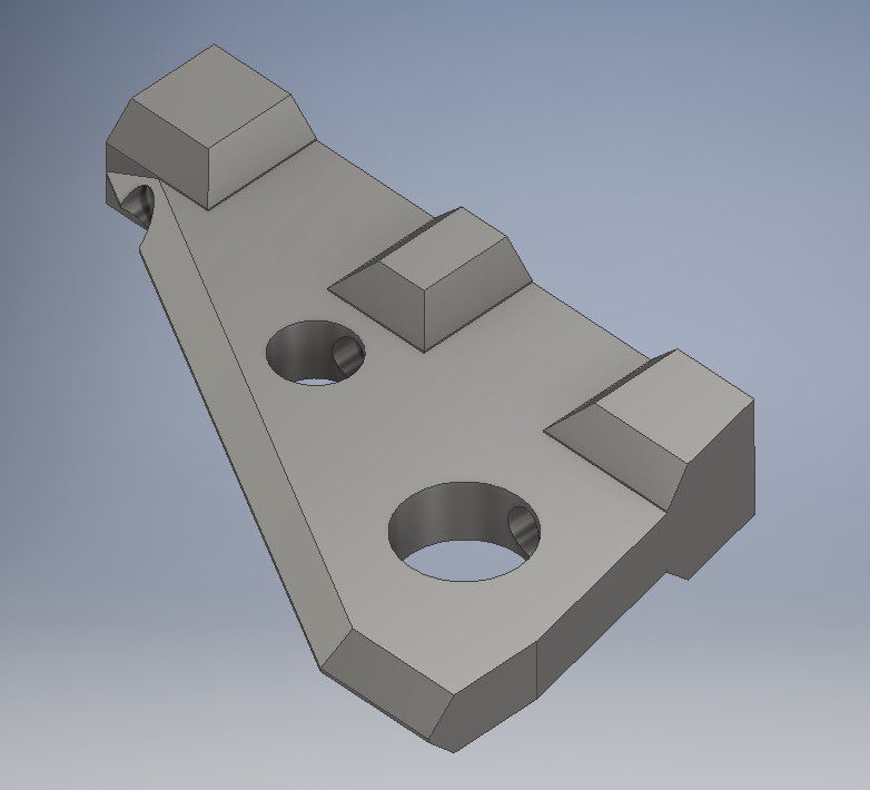
Flipping the bolt hole was a good decision. Adding that flip increased the base by almost an inch, which increased the strength of the ring. This is the iteration that we will be fighting with, so I’ll go into more details with this one.

Third Iteration: Hollow and Flipped Bolt Hole
Why does the arm that hangs off the back work? The best analogy that I can create is someone shoving you. If you are standing with your feet together, and someone gives you a good shove, you will probably fall over. The base provided by your feet together is too small. If you stand with your feet as far apart as they can go and you get a shove, one foot pushes harder down into the ground, while your other foot starts to lift. This is a similar concept to how the arm works. As the impact comes in from the right, the bending moment that gets applied is spread out over a larger area, reducing the overall force on the ring.
I setup the FEA with this model, and ran it.
Third Iteration FEA Showing a Gap between the tooth and the root.
Remember how I said that I was planning on using a better contact set in the future? This is where it starts. If you look at the simulation results above, you can just barely make out a gap between the tooth and the ring. This is a good thing. Why? The connection between the ring and the tooth is a bolted connection, which behaves similarly to stapling two papers together. If I staple two pieces of paper together, I can still peel the pieces of paper apart, but they won’t slide past each other. The staple analogy behaves pretty close to a simple bolted connection. I used a “separation, no sliding” contact between the ring and the tooth to ensure that the faces could separate, but wouldn’t slide. I then “bonded” the bolt holes together to simulate the bolt holding those faces together. Using the bonding contact does introduce some problems in.
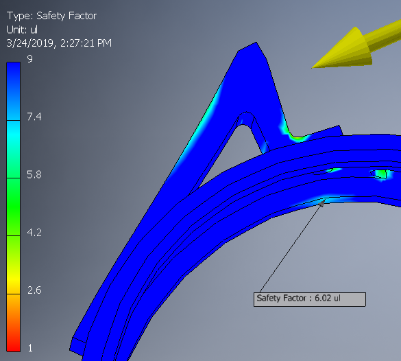
Third Iteration FEA FOS
The minimum factor of safety on this design is actually extremely small. It’s 0.29, and occurs right at the intersection of the bolt holes. This is a simulation artifact that I am choosing to ignore. Sharp corners near bonded faces usually end up getting large stresses shown, because the faces are perfectly bonded together in the simulation. This causes the math to freak out.
As can be seen, the factor of safety on the ring right at the base is now 6, in comparison to the meager 0.93 that it was in the previous model. The force on the tooth is the same. The pure blue that is shown is the maximum factor of safety shown. In actuality, most of the FOS is over 40 because the stress on the ring is so low in most locations. With an FOS that high, the lower end in the 1 to 5 range becomes really compressed, so everything looks red. I shrunk the scale down to make it easier to see what was going on, as seeing a super high FOS is not that useful.
With hollowing out the tooth, this tooth is 0.253 pounds, in comparison to the previous tooth’s 0.209 pounds. Not bad for only increasing the mass of the tooth by 0.05 pounds and getting a six-times strength increase.
Iteration 3+: I’m Not Quite Done Yet
I can’t leave anything alone. I just have to improve on that tooth design. Overall, there are some weight savings that are occurring on Halo. We wanted to be able to target 3 pound and 1.5 kg competitions, but that leaves us with some mass available to play with. Well, what does that mean for this design? The answer: bigger and badder teeth. Meet iterations 3+ and 3++.
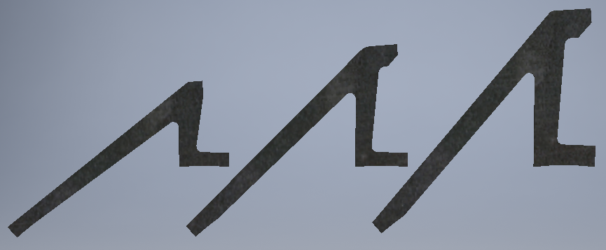
Halo Third Tooth Iterations
Each tooth is respectively 0.253, 0.330, and 0.451 pounds. I’m hoping that I can use the largest tooth because that results in the largest bite and available kinetic energy. If either of the larger teeth are too heavy, we can also grind down the fang at the end to reduce the weight into spec. Other than that, they are all identical, so we can swap in any tooth to meet weight.
Do these teeth work? I’ll leave that for you to decide. Here are the FEA results for the large tooth.
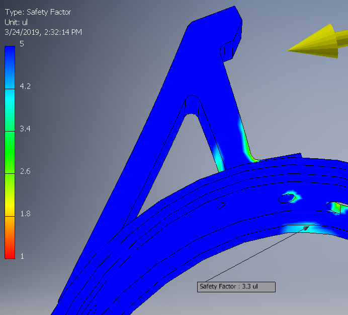
Even with the largest tooth, we still get a factor of safety of safety of 3 with a 300 pound load at the end of the tooth. That should hopefully allow us to last a full competition without the ring cracking.
The result: a pretty terrifying set of numbers.
Overall Bot Radius: 7.75 inches
Ring Radius: 5 inches
Resulting Bite: 2.75 inches (35% of total radius)
Top Speed: 1100 RPM
Tip Speed: 75 fps (50 MPH)
Total Energy Stored @ 1100 RPM: 250 Joules
Meet Halo V2. Terrifying, even for us.