So here’s what happened
Say you get to know a guy, by say, building a terrifying blimp with him. Say he tells you he can get you a one-time deal: free 5mm titanium sheets, with free lasercutting thrown in. Just send him a DXF and he’ll make it happen. What would you do?
I know I would make a silly battlebot!

Antweight Meltybrain!
When I spoiled this on reddit, I got a few people saying “One wheel? How?”. The truth is: meltybrains only need one wheel to spin! Translation is achieved from the wheels spinning faster on one side of the rotation than the other, which can be done with any number of wheels.
Now, that’s not to say two wheels aren’t helpful. Two wheels means double the power. It means faster startup time, since no part of the bot has to be dragged on the ground. It means that you can drive the bot in standard arcade mode. And it means you can lose a wheel and still keep spinning.
But this is an antweight! Ain’t nobody got weight for two wheels.
Design Criteria
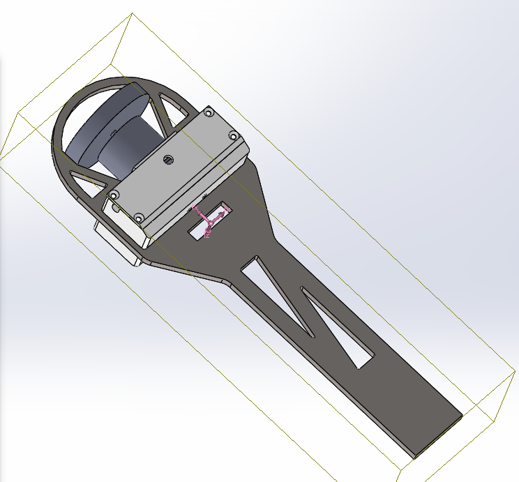
3D model view, with center of mass overlay
I started from “I want to make tombstone except just the spinning bits”. By going with one wheel, it would be easier to stay within weight, and it meant I could use common motors/wheels/esc’s with Halo (yay common spare parts piles!).
Of course, the challenge with a design like this is the electronics aren’t as well protected as in Halo. The safest place is the center of rotation, but anything sitting there contributes very little to rotational inertia (read: hitting power). I eventually settled on the counterweight/blade approach. The counterweight (electronics, wheel) is very dense, and the blade is relatively less-dense. This means the blade stretches further from the center of rotation than the counterweight does. The tip of the blade to the center of rotation is 183mm, as opposed to 108mm to the end of the wheel guard. Doing the math, an enemy bot has to make it 75mm into Hit ‘N Spin without striking the blade before the squishy electronics are threatened. I’ll take those odds!
Design Implementation
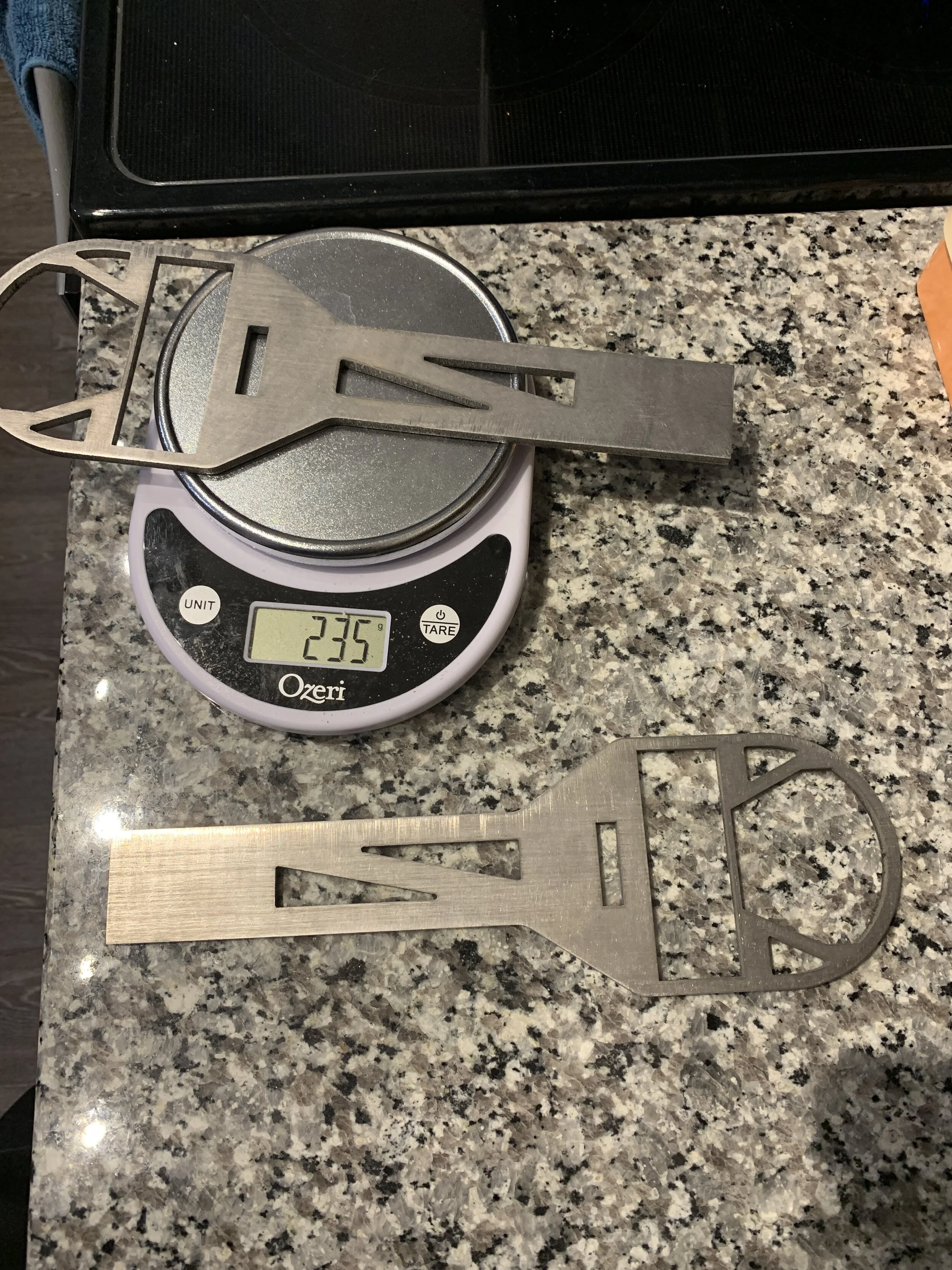
Yup. It’s titanium
The blade is lasercut from some 5mm scrap titanium sheet. The design of the blade was the primary method I had to control the center of mass.
The Enclosure
The electronics box is printed around the titanium to save on fasteners and space. This is a fun trick with 3D printers; a carefully designed printed object can have things inserted during the print.
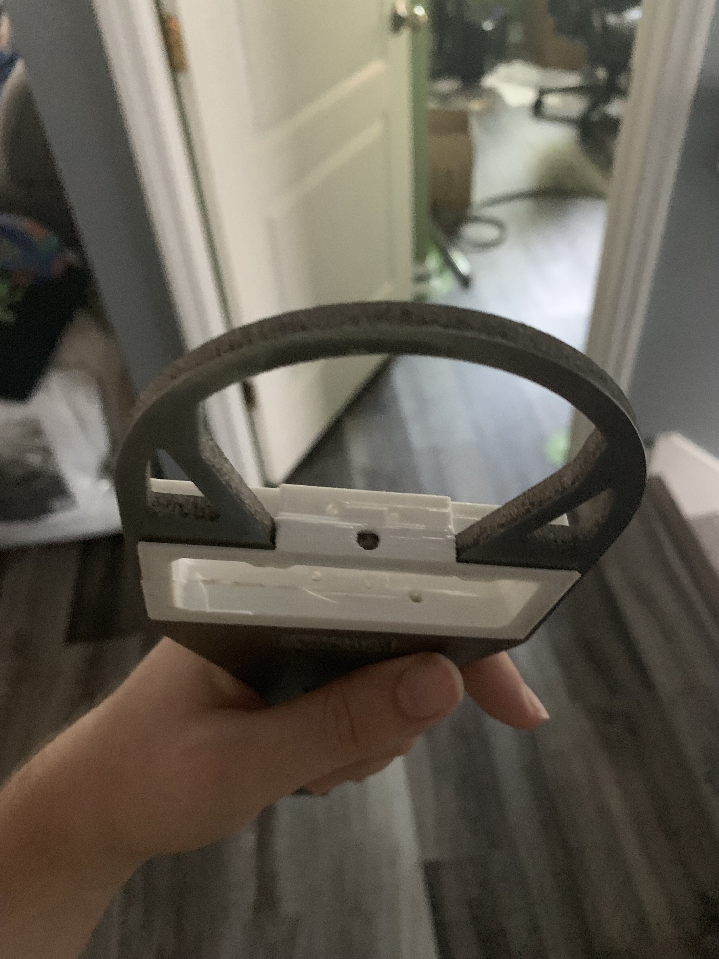
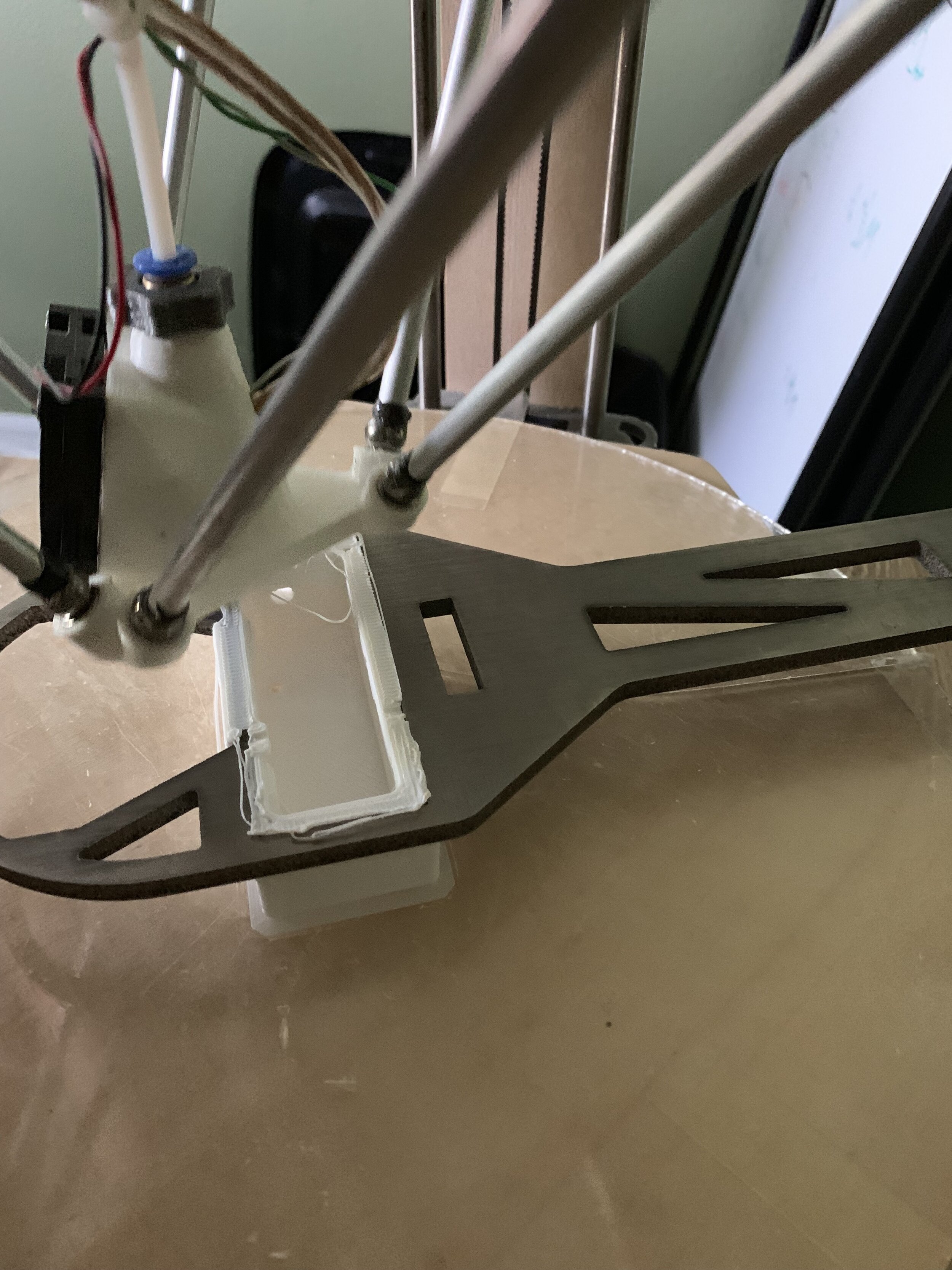
People usually insert bolts or bearings into an object rather than a giant titanium blade. But the concept works the same. The result is an enclosure that is totally captive to the titanium, without any fasteners at all.
The cost is that you can’t really have spare enclosures. It can only be printed on, which isn’t realistic at a competition. We’ll see how much of a problem this actually is at Robot Ruckus.
The motor bolts right into the plastic enclosure. Bolting into plastic isn’t my favorite thing to do, but hey, it’s an antweight. I didn’t have the weight or space for much else.
Spinup considerations
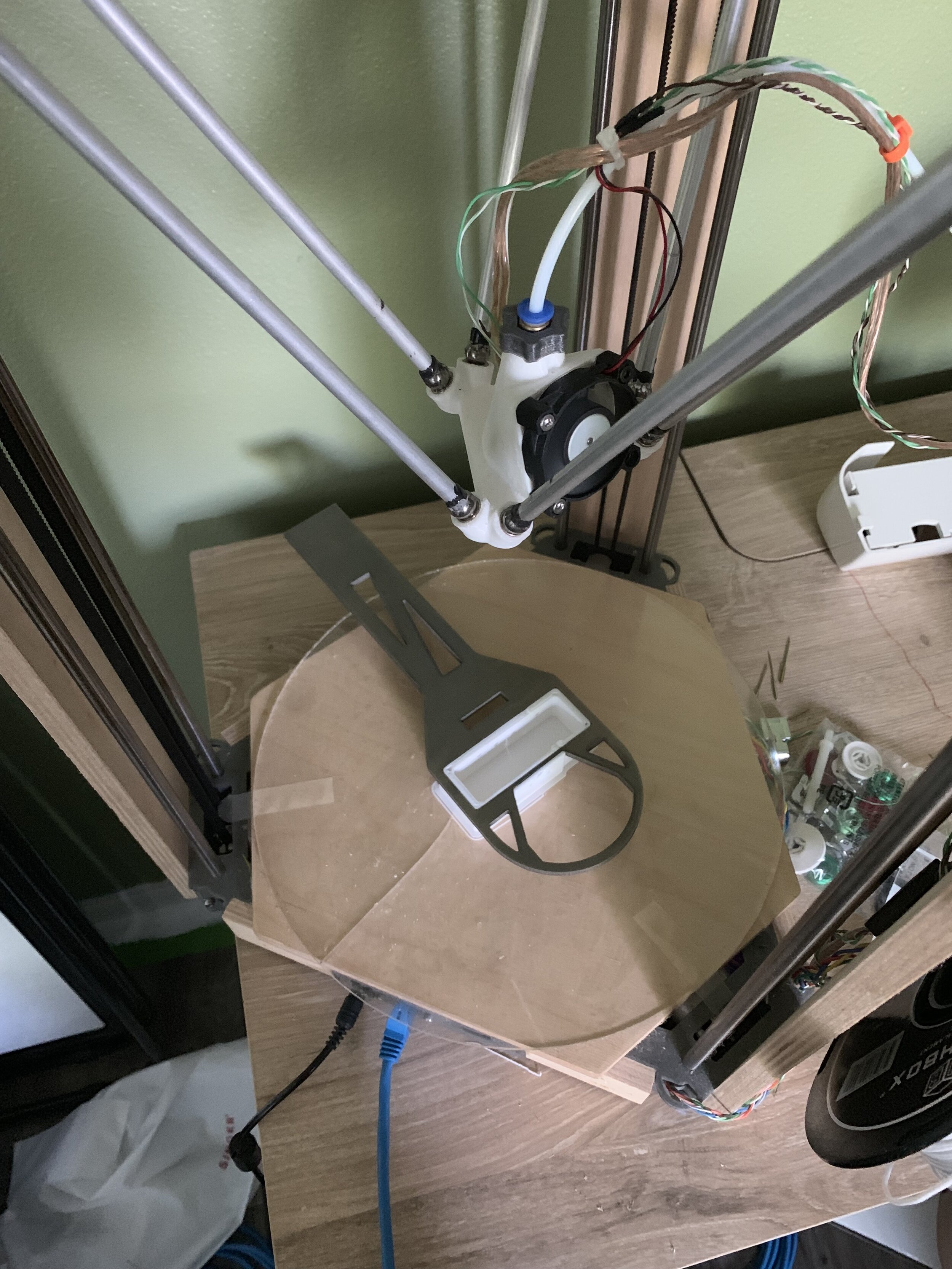
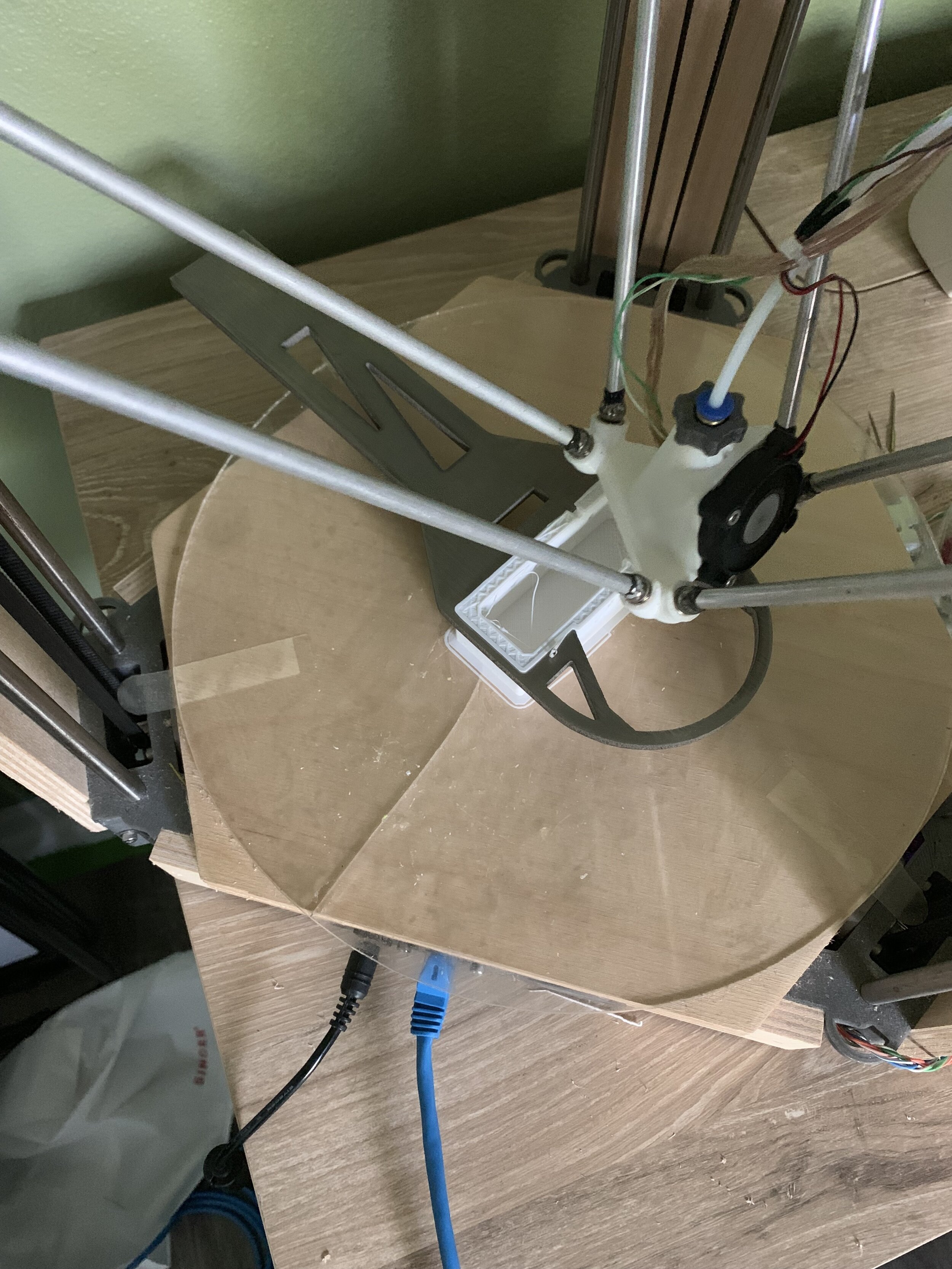
Spinning up is strange due to just having one wheel. At first I planned on having some kind of post or pad for the bot to spin around (hence the cutout around the center of mass).
In practice, I didn’t have to add anything. At rest, the bot touches the ground by the wheel and the end of the blade. When the bot starts spinning up, it rotates around the end of the blade. This is great, as it’s a longer lever arm (meaning more torque to spin up faster). After the bot gets some speed, the blade slips along the ground, and the bot starts rotating around the center of mass. Meanwhile, the centripetal acceleration pulls the blade up, making the wheel the only thing in contact with the ground.
The blade stays low to the ground, making Hit ‘N Spin a kind of undercutting spinner.
Pursuing this strategy lead to an unexpected design constraint: the enclosure must not touch the ground when resting on the blade. Otherwise the bot high-centers, holding the wheel uselessly off the ground. I had to iterate the enclosure several times to make sure I had enough ground clearance.
Electronics
I had to jam an ESC, circuit board (with radio), battery, breaker, fuse, and connecting wire into a tiny box. My strategy was to use the circuit board to integrate as much of that as I could.

The guts spilling out of an earlier version.
The circuit board I came up with has a fingertech breaker and 15A SMD fuse soldered right on. It has the display leds on top and bottom, the IR reciever diode looking out one side, and solder holes for the battery wires and ESC wires. I kept the meltybrain electronics the same as Halo.
The beauty of a custom circuit board here is
1) Routing connections on a PCB is way easier, lighter, and more space efficient than using normal wire.
2) I can position all of the location-sensitive components extremely precisely. When the board is inserted, everything magically lines up.
3) By providing extra solder holes, I don’t need to splice or T any external wire. Every wire is point-to-point.
Sure, designing a PCB is a lot more work up-front. But wow does it save you effort when you go to put everything together.

Everything jammed in
The PCB Schematic
Can be found here. I kept it as simple as I could, as I didn’t have space or weight for any fancy experiments. There was one exception: I added a LIS3MDL 3-axis magnetometer.
Quick aside: magnetometer testing
I had to at least try it. Supposedly, you can measure the earth’s magnetic field to get an absolute direction reference.
But I’ve worked with magnetometers before, and I know the truth. They are horribly noisy, and prone to getting messed up by everything. Motor turns on? your measurement gets biased. Steel object comes close? Biased. Route a trace wrong on your circuit board? Noise.
I put a magnetometer on Hit ‘N Spin (U1), and recorded the readings while I slowly spun the bot by hand. The data was just too imprecise to be useful. Unless you’re an expert on the subject, I wouldn’t try this at home.
The Layout

Done in KiCad 5.0
It’s a four-layer PCB, signal-ground-3.3V-signal. I had it manufactured at OSHPark. Note the lack of mounting holes! I removed them after I realized it was impossible to tighten a bolt in, and the board was already held in pretty well by the battery and cover.
Software
The code can be found here: https://github.com/swallenhardware/MeltyHitNSpinV1_1
This is a pared-down fork of the Halo codebase. On a basic level, it runs the same. But I don’t have a POV text display, and I only have one motor to control. I also had to re-calibrate the accelerometer, the data from which is below:

Calibration data and best-fit
From the data, it appears Hit ‘N Spin maxes out at ~1300RPM. That’s pretty good!
Test Video!
Expectations
With both a lower rotational inertia per lb and lower top speed, I don’t expect Hit ‘N Spin to be the brutal slugger Halo is. I’m expecting Hit ‘N Spin to put on a good show. It’s a silly looking robot, and it’s pretty chaotic to drive. If it ends up in the pit twice, I’ll be happy as long as it got cheers doing so.