You can find the full code here. Read on for a discussion on how it works!
I had originally planned testing controls code with the robot on it's own two wheels. But after a catastrophic failure in one of said wheels, it was determined I would need to wait for my partner to machine some new ones out of aluminum. That would take too long, so I picked up some clamps and printed a test stand.

Test stand in place, I started working on the code in earnest.

The overall code structure follows the block diagram above. I wont go into detail on how I implemented every feature. Hopefully comments in my code can handle that. Instead, I'll go through the architecture here.
The State Machine
The main state machine is composed of three states: idle, tank, and spin.
Idle is the "safe mode" the the robot reverts to if there is a problem or if the dead-man switch is released. In this mode the motors are set to 0 speed. I originally tristated the motor outputs using my voltage-level translator, but found it caused odd behavior in my ESCs so I now only manipulate the speed.
When the robot is enabled, it transitions to either "spin" or "tank" depending on the throttle slider. If the throttle is very near 0 it goes to tank, otherwise it starts up in spin. The robot reverts back to idle if the communications time out or the dead-man switch is released.
Tank mode allows the robot to be controlled like a ram bot. This is good for testing and as a backup in case for some reason spinning is ineffective. It's a bit of a misnomer, as I actually use arcade controls in this mode, but the name stuck.
While in spin mode, the robot begins reading from the accelerometer and the beacon to determine the real-time heading. It also powers the motors as allowed by the throttle command, and taking account steering pulses.
The Math
While the bot is in spin mode, it is constantly running math to figure out where it's pointing. I've been pretty nebulous about it thus far, but I'll do my best to explain it here. First I'll focus on using the infrared beacon.
Infrared Beacon Only Sensing
Say your robot is rotating, and you have a perfect beacon system that generates a positive edge (goes from low to high) once per rotation. You record the times of two edges. Since we know every edge must be 360º away from the last one, we can plot these edges on a graph

Looks like the robot is rotating at one revolution per second. Now, a little later, the robot tries to figure out where it's pointed. We only know the graph above, and the current time.

To find which way we are pointing now, we just extend that blue line, and find where it crosses the red dotted line.

Now for an equation form of this method (with thanks to wikipedia).
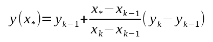
X in our case represents time, and y represents distance in degrees. The earliest point measured is (x_k-1, y_k-1), the latest point measured is (x_k, y_k), and the current position is (x_star, y). We can simplify this a lot by realizing that our previous two points were 360º apart in y. For simplification, lets say point one is at (t1, -360º) and point two is at (t2, 0º). The current time is t3.
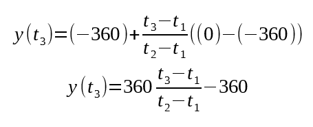
And that's our final equation. Here's what it looks like in code form:

Where newTime is the current time, beaconEdgeTime[0] is the latest edge time, and beaconEdgeTime[1] is the edge time before that. I replaced the last minus sign with a modulous to make sure the angle never goes above 360º.
This system works great for if have just an infrared beacon. However, if your robot accelerates or decelerates during a revolution, the code above will not account for that and error will be introduced until the next beacon edge.
Accelerometer Only Sensing
Accelerometers measure the rotation speed of the bot by measuring centripetal acceleration (a_c).

Where omega is rotational velocity and r is the distance from the center to the accelerometer. This is unlike the beacon, which measures the rotational position of the robot directly. The benefit, however, is we can make measurements constantly, not once per revolution as before.
If the accelerometer is mounted against the ring wall as in our design, the z-axis (which looks radial to the ring) is your centripetal acceleration. In addition, the other axis have value for us. the axis axial to the ring (up and down when the ring is flat on the ground) measures only gravity, so it can tell us if the bot has been flipped over. The axis tangential to the ring tells us the acceleration of the ring, which an advanced programmer can use like a gyroscope to improve our algorithm.
To turn a speed measurement into a position measurement, we need to use some concepts from calculus. We can relate speed and position using:

Where Θ is angular position. These equations let us make a perfect measurement of distance from speed. Unfortunately, they require us having knowledge of the speed at all times, and we only have periodic measurements available. But if we replace the 'd's with deltas, we can get close to the correct value.
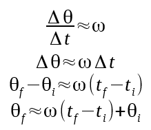
Θf is the current angle of the robot, omega is the last measured speed, tf is the current time, ti is the time of the last measurement, and Θi is the angle of the robot at the last measurement point.
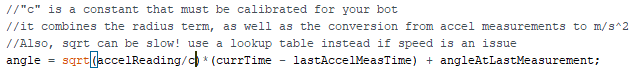
The final equation above is the most basic way to measure position using an accelerometer. The catch is that there was a certain amount of error introduced when we turned the d's into deltas. That error builds up and causes your angles to drift over time.
Here's a code implementation:
Hybrid Sensing
If you are looking for the best of both worlds, accelerometers and beacons pair together easily. The best way to do this is to code the bot as if it was accelerometer only, but 0 the angle every time you see a beacon edge. This allows for real-time speed measurement without error build up problems.
You can also use this system to prevent beacon miss-triggers from confusing your bot. This is possible by checking your accelerometer-measured heading every time a beacon edge is recorded. If the edge occurred way faster than the accelerometer was expecting, you can safely ignore it.
Thanks to teammate Novia Berriel for working out the math